NewsNEWCENTER
Featured products
Contact Us
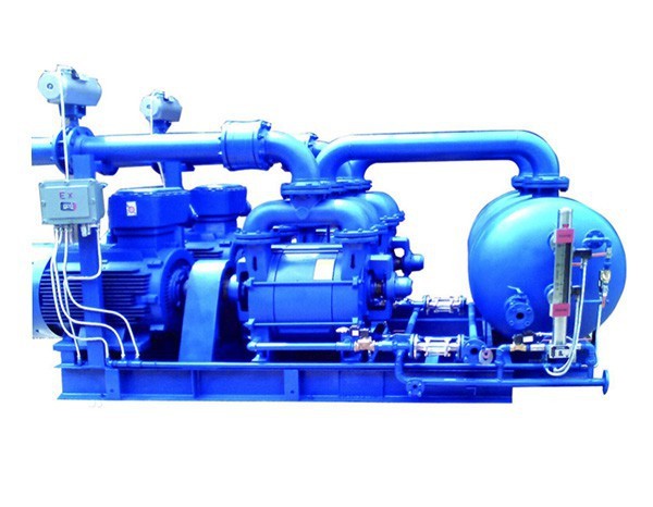
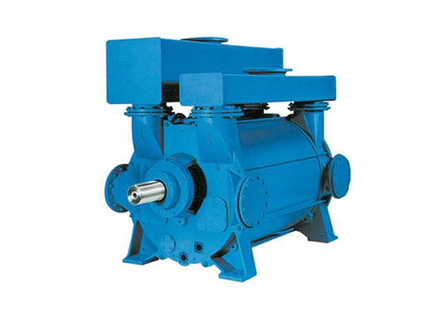
How a Water Ring Vacuum Pump Works
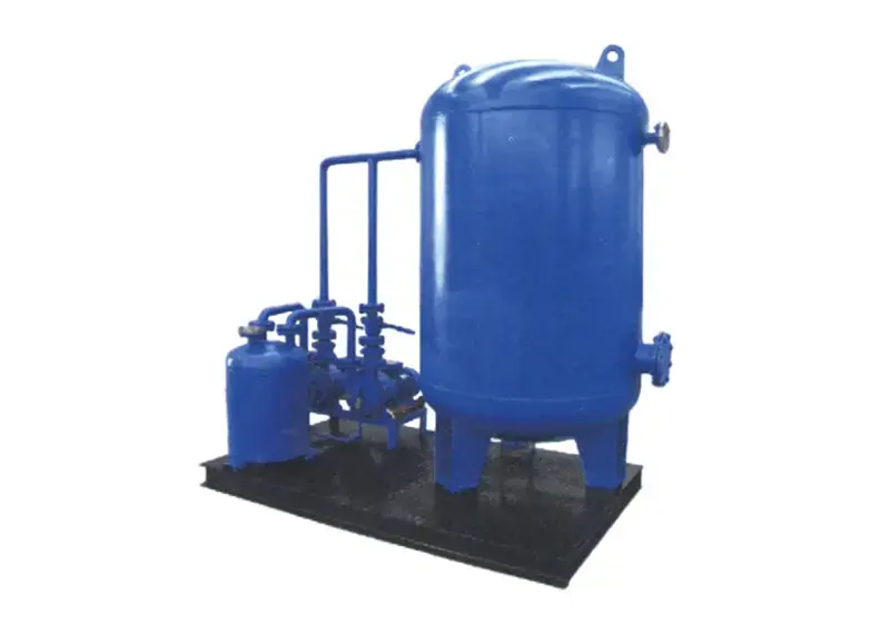
2026-05-07Water ring vacuum pumps have a maximum vacuum of 2,000–4,000 Pa, and when integrated into a vacuum pump system, they can achieve a vacuum level of 1–600 Pa. Through continuous product upgrades, the performance of this equipment has become exceptionally superior, offering advantages not found in other products. To help you better understand, the following section explains the working principle of water ring vacuum pumps.
Water ring vacuum pumps were initially used as self-priming water pumps but have since been increasingly applied in numerous industrial sectors, including petroleum, chemicals, machinery, mining, light industry, pharmaceuticals, and food processing. They are widely used in many industrial production processes, such as vacuum filtration, vacuum water supply, vacuum feeding, vacuum evaporation, vacuum concentration, vacuum rehumidification, and vacuum degassing. Due to the rapid advancement of vacuum application technology, water ring pumps have long been valued for their ability to achieve rough vacuum. Since gas compression in water ring pumps is isothermal, they can handle flammable and explosive gases. Additionally, they can handle gases containing dust or moisture, leading to their increasing use.
An appropriate amount of water is installed in the pump body as the working fluid. When the impeller rotates clockwise in the indicated direction, the water is flung outward by the impeller. Due to centrifugal force, the water forms a closed ring of approximately uniform thickness, the shape of which is determined by the pump chamber. The inner surface of the upper part of the water ring is tangent to the impeller hub, while the inner surface of the lower part of the water ring just touches the tips of the blades (in practice, the blades have a certain depth of penetration into the water ring). At this point, a crescent-shaped space is formed between the impeller hub and the water ring, and this space is further divided by the impeller into several small chambers, each corresponding to the number of blades. If the upper 0° of the impeller is taken as the starting point, the volume of the small chamber increases as the impeller rotates through the first 180°, and it communicates with the suction port on the end face; at this point, gas is drawn in. When suction is complete, the small chamber is isolated from the suction port; As the impeller continues to rotate, the volume of the small chamber decreases, compressing the gas; when the chamber communicates with the discharge port, the gas is expelled from the pump.